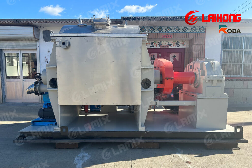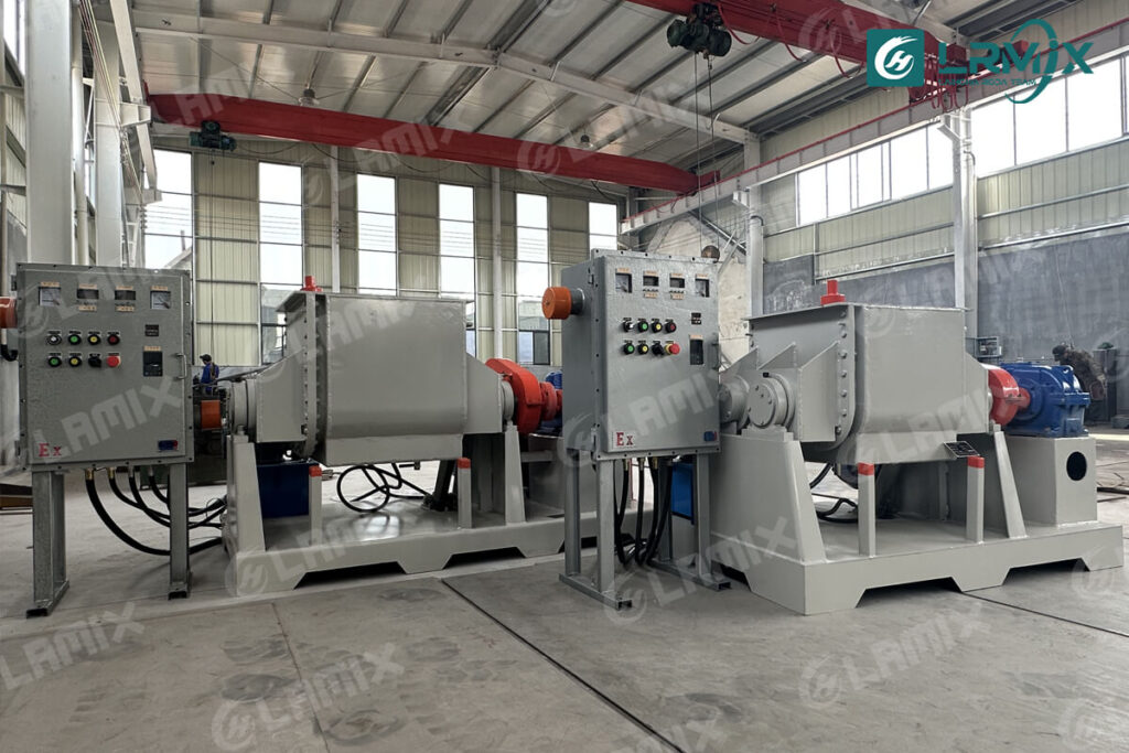
For small to mid-scale silicone rubber production — pilot operations, multi-formula compounding, and production lines running 3 to 8 batches per shift — a 200L sigma kneader is a practical and cost-effective unit. It is large enough to supply a calender or extrusion line at moderate throughput, and small enough to maintain process flexibility when formulations change frequently.
This article covers the configuration decisions that matter when specifying a 200L sigma kneader for HTV silicone rubber production: cooling method, vacuum system design, contact surface specification, blade cooling considerations, and discharge. Each choice has a direct consequence on compound quality and production efficiency.
Note: For large-scale silicone rubber production lines — 1,000L to 3,000L batch capacity — the heat transfer considerations change significantly. At that scale, jacket cooling alone is often insufficient to maintain compound temperature during high-loading fumed silica incorporation. Blade cooling channels become a standard requirement rather than an option. This is covered in the blade cooling section below.
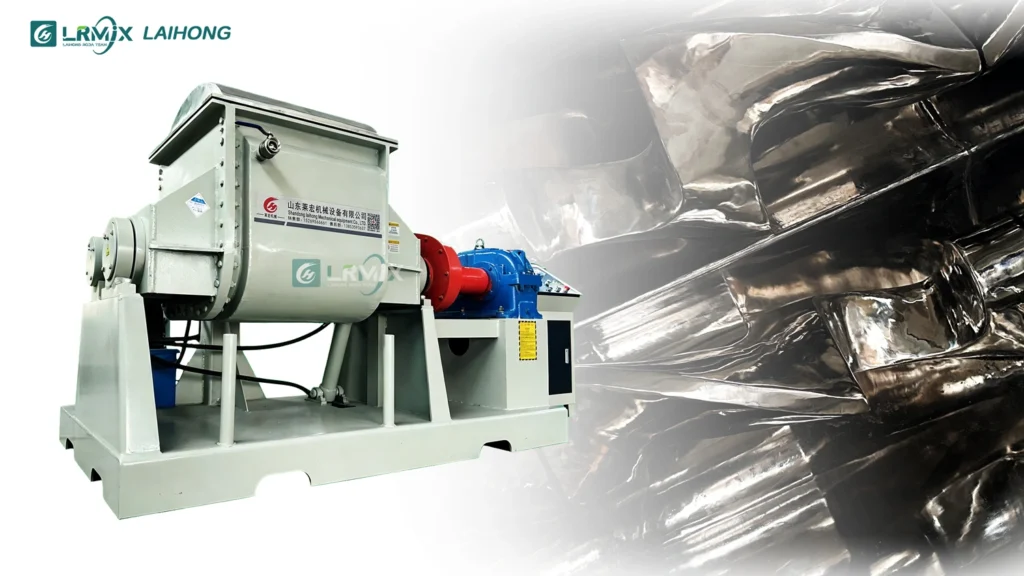
Why Silicone Rubber Places Specific Demands on the Kneader
HTV silicone rubber is built on a polydimethylsiloxane base polymer with a molecular weight typically between 400,000 and 800,000 g/mol. At room temperature, this material has an elastic, dough-like consistency that resists flow and generates significant friction when the sigma blades work through it. As fumed silica — the primary reinforcing filler, typically loaded at 20–45 phr — is incorporated, two problems develop simultaneously.
First, the friction between blades, compound, and filler generates heat. Without active cooling, vessel wall temperature at 200L scale can exceed 60°C within the first 20 minutes of a fumed silica addition cycle. Peroxide vulcanising agents used in HTV silicone — dicumyl peroxide (DCP) and others — begin thermal decomposition well before their stated activation temperatures, especially under sustained exposure. The practical consequence is scorch: premature crosslinking that converts a portion of the batch into an unusable gel before the mixing cycle is complete.
Second, fumed silica grades used in silicone rubber compounding — such as those with BET surface areas of 150–400 m²/g — entrap significant volumes of air during incorporation. This air does not self-release at ambient pressure in a viscous matrix. It remains as micro-voids distributed through the compound. In the cured product, these voids become the initiation sites for surface pitting, reduced tear strength, and in applications such as medical tubing or optical sealing compounds, outright rejection.
A 200L sigma kneader configured for silicone rubber production must address both problems within a single machine.
Cooling Jacket Design for Large-Batch Silicone Compounding
At 200L working volume, the ratio of vessel wall surface area to batch mass is lower than at smaller scales. The same heat-transfer area serves a larger mass of compound. This means that cooling water flow rate, jacket design, and temperature differential between coolant and compound all carry more weight in the specification than they do at 50L or 100L scale.
The cooling jacket on a production 200L kneader should be designed for circulation rather than static fill. A baffled jacket with defined inlet and outlet positions — sized for the actual flow rate of the chilled water circuit — transfers heat more consistently than a plain water jacket with unpredictable flow paths. The practical target during fumed silica addition is to maintain compound temperature below 50°C at the vessel wall. This is not a conservative specification: it provides a margin between the operating condition and the onset of peroxide activation while accounting for the fact that compound temperature near the centre of the batch will lag behind the wall measurement.
Some silicone compounders operate with a single cooling circuit connected to a plant chilled water supply. Others use a dedicated chiller unit, which allows the outlet temperature to be set independently of plant conditions and provides more consistent batch-to-batch performance. Either approach works, but the kneader jacket must be compatible with the flow rate and pressure of the available cooling system.
Vacuum System: Timing, Depth, and Seal Integrity
The vacuum system on a production sigma kneader for silicone rubber serves one purpose: removing air that the blade action alone cannot expel. The mechanism is straightforward — reducing pressure above the batch lowers the internal pressure of entrapped air bubbles, causing them to expand toward the free surface where the blade action can rupture and release them.
Three parameters define whether a vacuum system will achieve this:
Vacuum depth. For silicone rubber compounding, a working vacuum of –0.085 to –0.095 MPa (gauge) is the standard operating range. Shallower vacuum — above –0.07 MPa — may not produce sufficient bubble expansion in a high-viscosity matrix at elevated loading. The vacuum pump must be sized for the vessel volume and the expected leak rate through the shaft seals and cover gasket at working temperature.
Timing within the batch cycle. Applying vacuum before the fumed silica is substantially incorporated is generally counterproductive: the free surface is not yet developed enough for bubbles to migrate and release, and the high surface area of unwetted filler can cause dusting into the vacuum line. The effective vacuum window is after the compound has reached a cohesive, homogeneous state — typically 15–25 minutes before the end of the main mixing cycle, depending on formulation. This timing should be established from batch trials and held consistent across production.
Seal integrity under production conditions. A vacuum chamber that holds –0.09 MPa in a factory acceptance test will degrade over time if shaft seals are not maintained. At 200L production scale, where multiple batches run per shift, the mechanical seal arrangement at both blade shafts and the cover gasket material are maintenance items that should be specified in the purchase documentation — not assumptions.
Mirror-Polished SS304 Contact Surfaces: What the Specification Means in Practice
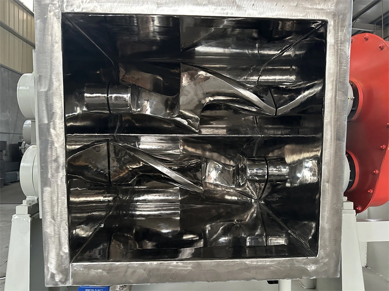
A mirror-polished interior is not an aesthetic option on a production kneader for silicone rubber. It is a functional specification that affects three aspects of production: material release, cleaning time, and contamination control.
Material release matters at 200L scale because the silicone compound in contact with the vessel wall and blade surfaces during mixing develops adhesion. A rough or machined surface finish creates mechanical interlock points where compound bonds to the surface. At the end of a batch, this material does not discharge cleanly with the rest of the compound — it remains on the surfaces as a residue layer. At a surface roughness of Ra ≤ 0.4 μm, this interlocking mechanism is substantially reduced. The compound releases more completely, discharge residue is lower, and the quantity of compound that must be manually removed between batches decreases.
Cleaning time between batches is a direct production efficiency variable. A mirror-polished interior — particularly on the blade surfaces and the trough radius where compound accumulates — can reduce inter-batch cleaning time significantly compared to a standard machined finish. At a high-output silicone compounding operation running multiple batches per day, this time saving accumulates.
Contamination control addresses a separate issue. Carbon steel oxidises progressively under the temperature and humidity conditions of a mixing operation. Even SS304 contact surfaces will stain if cleaning chemistry is incompatible or if chloride-bearing water contacts the surface repeatedly. The practical specification should include the surface finish (Ra ≤ 0.4 μm), the electropolishing or mechanical polishing method, and the cleaning procedure that maintains the finish over the equipment lifetime.
Blade Cooling Channels and Rotary Joints: Optional at 200L, Essential at Large Scale
Standard sigma kneaders cool the compound through the vessel wall only. The blade surfaces — in direct and continuous contact with the compound — are not actively cooled. In a 200L vessel, the jacket surface area is generally sufficient to manage compound temperature during fumed silica incorporation, provided the cooling circuit is correctly specified and the coolant temperature is maintained.
At 200L scale, blade cooling channels are an option worth considering for specific situations — high fumed silica loadings above 35 phr, aggressive batch cycle schedules, or formulations using very-high-surface-area silica grades. Where these conditions are not present, optimising the jacket cooling circuit is the more practical and cost-effective starting point.
The picture changes fundamentally at large-scale production.
For sigma kneaders in the 1,000L to 3,000L range used in high-volume silicone rubber compounding, the ratio of jacket surface area to batch mass decreases significantly compared to a 200L unit. A 2,000L kneader processing 1,200–1,400 kg of silicone rubber compound with 30–40 phr fumed silica loading generates heat at a rate that a jacket alone cannot reliably dissipate within a controlled cycle time. Compound temperature in the centre of a large batch lags far behind the wall temperature — and it is the centre temperature that determines whether peroxide vulcanising agents are safe.
Blade cooling channels become a standard specification requirement at this scale, not an optional upgrade. Coolant — typically chilled water at 8–15°C — circulates through channels machined within the blade body, entering and exiting through rotary joints at the shaft ends. This adds a heat transfer surface distributed through the compound mass itself, rather than concentrated at the vessel wall. The practical result is a more uniform temperature profile across the batch and a reliable ability to maintain compound temperature below 50°C even at sustained high fumed silica loading.
Rotary joints are rotating mechanical seals and require periodic inspection and replacement. In a large-scale production environment, this maintenance interval should be included in the equipment specification and planned maintenance schedule from the outset.’
Hydraulic Tilt Discharge at 200L Scale
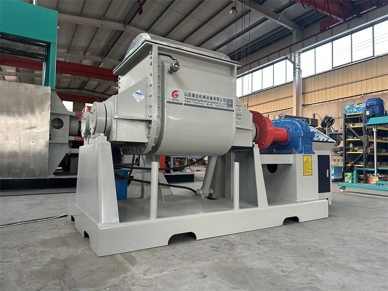
At 200L working volume, the batch mass of silicone rubber compound is typically 140–160 kg. Manual discharge of this quantity — even with auxiliary tools — takes two operators 20–30 minutes and leaves residue that varies between batches. Hydraulic tilt discharge at 130° is the standard solution for production-scale silicone kneaders.
The hydraulic system tilts the vessel under controlled speed. At 130°, the compound flows out under gravity, assisted by its own weight. For standard silicone rubber compounds at the end of a normal mixing cycle — when compound temperature is controlled and the material is in its cohesive, plastic state — this produces clean discharge with minimal residue in 4–6 minutes. The discharge rate is consistent between batches because the tilt angle and vessel geometry are fixed.
Two details in the hydraulic tilt specification deserve attention at production scale. First, the tilt speed should be adjustable. Some silicone formulations — particularly at lower process temperatures or with high filler loading — flow more slowly, and a slow tilt speed prevents compound from slopping unevenly during discharge. Second, the vessel should return to the upright position under hydraulic power, not under gravity alone, to ensure consistent positioning for the next batch load.
Production Configuration Summary
For a 200L sigma kneader configured for HTV silicone rubber production, the following specification points address the process requirements described above:
Vessel volume: 200L nominal, 120–140L working volume for standard silicone rubber formulations Contact surfaces: SS304 stainless steel, mirror-polished Ra ≤ 0.4 μm, all product-contact parts including blades, trough, end plates and cover Vessel jacket: Cooling water circulation, baffled design for defined flow path, compatible with chilled water supply or dedicated chiller Blade cooling: Coolant channels within blade body, rotary joints at shaft ends — specify where fumed silica loading exceeds 35 phr or cycle time requirements are aggressive Vacuum system: Target operating vacuum –0.085 to –0.095 MPa gauge, pump sized for vessel volume, mechanical shaft seals with defined maintenance interval Discharge: Hydraulic tilt to 130°, adjustable tilt speed, powered return to upright
Custom configurations including steam heating, thermal oil, SS316L contact surfaces and explosion-proof electrical systems are available on request.
Contact LRMIX
WhatsApp: +86 198 1875 7839 Email: info@lrmixer.com Website: www.lrmixer.com
LRMIX — Sigma Kneader Manufacturer | Shandong, China | 40+ Countries